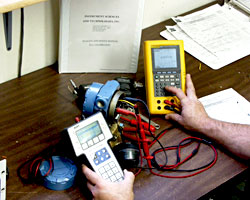
Many people do a field comparison check of two meters, and call them “calibrated” if they give the same reading. This isn’t calibration. It’s simply a field check. It can show you if there’s a problem, but it can’t show you which meter is right. If both meters are out of calibration by the same amount and in the same direction, it won’t show you anything. Nor will it show you any trending — you won’t know your instrument is headed for an “out of cal” condition. For a good calibration, the calibration masters should be better than the instrument has to be calibrated.
Calibration Method
The Calibration method of measurements requires instrument management. If one instrument said to be calibrated, it will be considered a method to ascertain management on instruments and find confidence.
The set of operations that establish, under specified conditions, the relationships between values indicated by a measuring instrument system or values delineated by material measure & the corresponding values of an amount complete by a reference normal is termed calibration.
Calibration methods involves checking the operational integrity of a test or measuring equipment or of a measurement standard of unverified accuracy in order to detect, correlate, report or eliminate (by adjustment) any deviation in accuracy, capability or from any other required performance. Calibration can be carried out for three possible purposes.
- Determining whether or not or not a selected instrument or standard is among some established tolerance in respect of its deviation from a reference standard.
- Reporting of deviations in measurements from nominal values.
- Repairing / adjusting the instrument or standard to bring it back among tolerance.
Why Accurate Calibration Method is needed
- Controlling the method, relation between inputs & output can be controlled
- To control the method, we need to know the status of the process
- Accurate measurement gives information regarding status
- Control of a process can never be better than the measurements made in the process
- The more accurate the data obtained from the process, with more accuracy the process can be controlled.
Causes of Calibration Issues
What knocks a digital instrument “out of cal?” 1st, the foremost elements of take a look at instruments (e.g., voltage references, input dividers, current shunts) will merely shift over time. This shifting is minor and frequently harmless if you retain a decent calibration schedule, and this shifting is often what calibration finds and corrects.
But, suppose you drop a current clamp — hard. How do you know that clamp will accurately measure, now? You don’t. It may well have gross calibration errors. Similarly, exposing to an overload can throw it off. Some people think this has little effect, because the inputs are fused or breaker-protected. But, those protection devices may not trip on a transient. Also, a large enough voltage input can jump across the input protection device entirely. This is far less likely with higher quality, which is one reason they are more cost-effective than the less expensive imports.

